E-mail: sachikoo_sz@yeah.net
Telephone: +86-13118819569

Views: 0 Author: Site Editor Publish Time: 2026-08-10 Origin: Site


Retrofitting security hardware into existing architecture requires absolute precision. Cutting into an unverified wall can compromise building structural integrity, sever vital utilities, or result in a safe that attackers can easily pry loose. Facility managers, contractors, and homeowners face a distinct dual challenge. You must ensure maximum physical security for stored valuables while mitigating the liability of damaging load-bearing elements or hidden infrastructure during the installation process. Structural failures and pierced plumbing lines lead to massive repair costs and severe safety hazards.
This guide provides a rigorous, evidence-based framework for pre-installation wall assessment. We detail exactly how to identify load-bearing structures before you pick up a saw. You will learn to map internal wall cavities accurately. Finally, we cover how to match specific wall dimensions and substrates to the correct security hardware, ensuring a flawless, secure installation.
Blueprint Verification is Mandatory: Identifying structural ("S") markers on architectural plans is the first line of defense against compromising load-bearing walls during installation.
Physical Joist Checks are the Ultimate Backup: When blueprints are missing, inspecting ceiling joists and basement beams is critical to identifying the building's load-bearing skeleton.
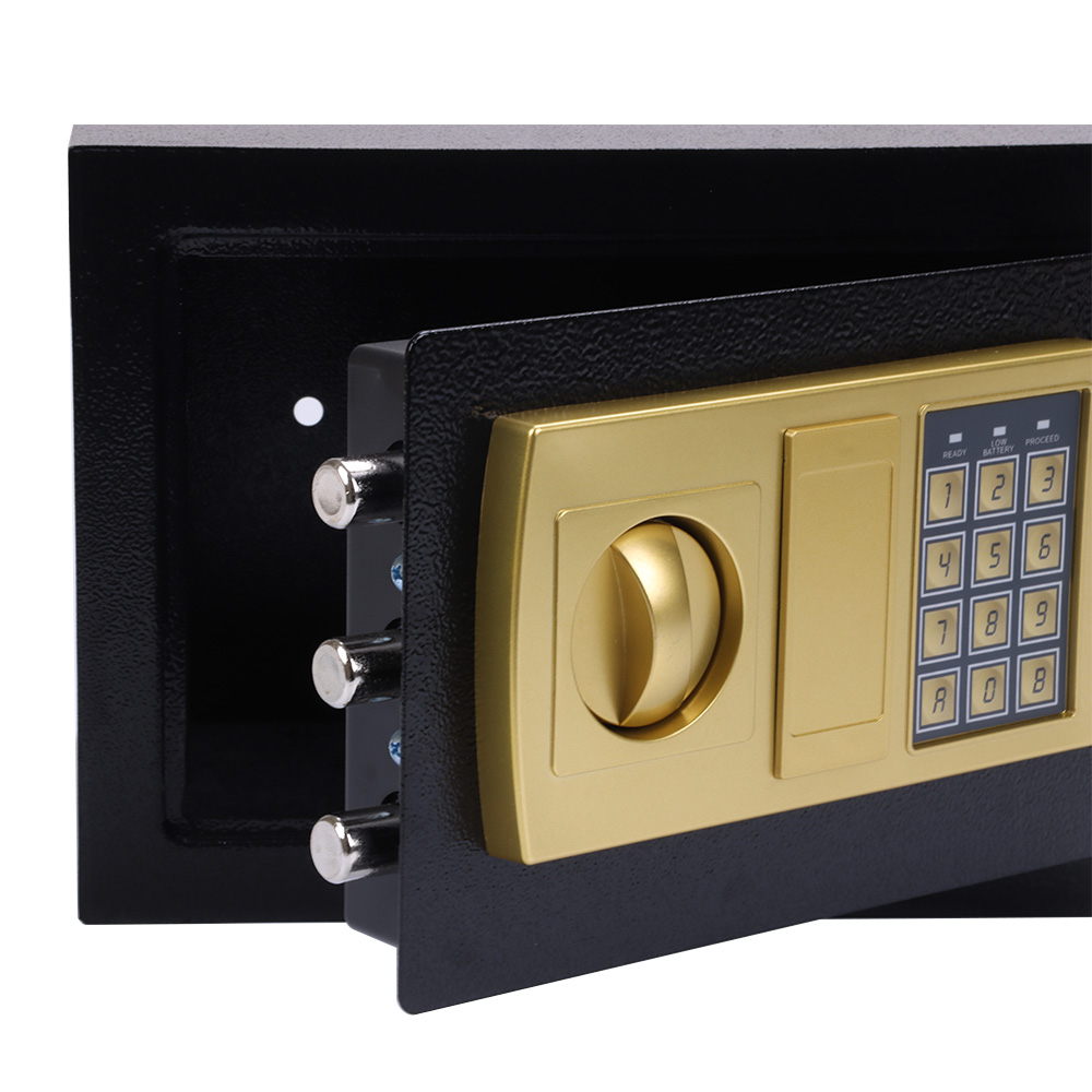
Cavity Depth and Stud Spacing Dictate Hardware: Standard 16-inch on-center framing restricts the dimensions of in-wall security solutions, directly impacting the viability of larger units like a laptop safe box.
Utility Mapping Prevents Catastrophe: Utilizing endoscopes, pre-drywall rough-in photos, and advanced stud finders is non-negotiable to avoid electrical, plumbing, and HVAC routing hidden behind drywall.
Substrate Determines Anchoring Efficacy: The structural integrity of the installation relies entirely on matching the mounting hardware to the wall material (wood stud, steel stud, or masonry).
Load-bearing walls function as the essential skeleton of any building. They actively transfer immense weight from the roof and upper floors directly down to the foundation. These walls handle constant compressive stress. Every stud within a load-bearing wall plays a specific role in maintaining the building's overall stability. The framing system relies on top plates, bottom plates, and vertical studs working in unison. Removing or altering these vertical supports disrupts the entire load path.
Severing or heavily notching load-bearing studs to accommodate a recessed wall mounted safe box introduces severe structural risks. Cutting a single load-bearing stud redistributes weight to adjacent studs. This often leads to immediate ceiling sagging. Over time, it causes drywall cracking, door frame binding, and potential localized structural failure. You compromise the safety of the entire floor above the installation site.
The baseline rule for recessed security installations is strict. Non-load-bearing partition walls remain the optimal choice. Partition walls simply divide interior spaces. They carry no structural weight other than their own drywall and framing. Cutting into a partition wall stud rarely impacts the building's structural health, making it the safest target for retrofitting security hardware.
A wall's shear strength directly dictates how much weight it can safely hold. You must account for the heavy steel chassis of the safe plus the maximum weight of its contents. Wood and steel studs possess high vertical load capacities. However, their ability to resist outward pull-out forces depends entirely on the anchoring method used during installation. If you fail to anchor the unit properly, the wall's structural capacity becomes irrelevant.
Improper anchoring creates a massive security flaw. Mounting heavy security hardware directly to weak half-inch drywall guarantees failure. Drywall possesses almost zero structural pull-out strength. Attackers do not need to pick the lock or crack the code. They simply use a pry bar to rip the entire unit out of the wall, taking your valuables with them to open later in a secondary location.
Securing the chassis directly to structural studs is non-negotiable. The heavy-duty lag bolts must penetrate the center of the wooden stud or properly engage the steel framing. This transfers the physical stress from the weak drywall to the building's robust framing. Proper stud anchoring ensures the unit remains firmly attached even under aggressive, sustained prying attacks.
Reading architectural blueprints and framing plans is the mandatory first step before any physical intervention. Blueprints provide a comprehensive map of the building's structural design. Locate the specific floor plan where you intend to install the unit. Look closely at the wall designations. Architects use specific symbols, line weights, and hatching patterns to differentiate partition walls from structural supports.
Pay immediate attention to any walls marked with an "S" designation. The "S" stands for Structural. This explicitly identifies a load-bearing wall. If your desired installation location falls on an "S" wall, you face a major hurdle. You must consult a licensed structural engineer if installation on this specific wall is absolutely unavoidable. They will design a structural header to safely redistribute the load around the new wall opening.
Pre-drywall inspection documentation offers immense value during this phase. Request any available photos or videos taken before the drywall was hung. These images reveal the exact locations of plumbing stacks, electrical runs, and HVAC rough-ins. Cross-referencing pre-drywall photos with your blueprints drastically reduces the risk of cutting into hidden, dangerous utilities.
Contractors frequently work in older buildings where original blueprints are long gone. When plans are unavailable, you must rely on physical building indicators. The most reliable method involves checking the orientation of the floor or ceiling joists. You can view ceiling joists from an unfinished attic. Floor joists are visible from an unfinished basement or crawlspace.
Follow these steps to verify joist orientation:
Access the unfinished space directly above or below the target wall.
Clear away any blown-in insulation to expose the wooden joists.
Observe the direction the joists run across the building span.
Determine the angle of your target wall relative to these joists.
Walls running perpendicular (at a 90-degree angle) to the joists are almost always load-bearing. They support the weight of the joists crossing over them. Conversely, walls running parallel to the joists are typically non-load-bearing partition walls. You must also identify central beams and exterior walls. Exterior walls form the primary load-bearing perimeter of the structure. Central beams run down the middle of the building. Any wall sitting directly above a central beam is load-bearing.
Framing materials vary significantly depending on the building type. Wood framing dominates residential construction. It utilizes solid 2x4 or 2x6 dimensional lumber. Commercial properties and hospitality venues rely almost exclusively on steel framing. Steel studs are lightweight, fire-resistant, and perfectly straight. However, they require completely different anchoring techniques compared to solid wood lumber.
Standard stud spacing dictates the maximum allowable width of your security hardware. Residential wood framing typically places studs 16 inches on-center. This leaves roughly 14.5 inches of usable space between the studs. Commercial steel framing often utilizes 24-inch on-center spacing. You must measure the exact stud spacing to ensure the safe chassis will physically fit between the vertical supports without requiring extensive reframing.
Mounting to light-gauge steel studs requires structural reinforcement. Steel studs are hollow and thin, often 20-gauge or 25-gauge metal. Heavy lag bolts will strip right out of the thin metal. You must install solid wood blocking inside the steel track or use specialized heavy-duty toggle anchors. This reinforcement prevents the steel stud from twisting or buckling under the cantilevered weight of the open steel door.
Standard wall cavity depths strictly limit your hardware selection. A wall framed with standard 2x4 lumber provides exactly 3.5 inches of internal depth behind the half-inch drywall. Walls framed with 2x6 lumber offer 5.5 inches of internal depth. You must measure the total depth from the face of the drywall to the back side of the opposite wall's drywall.
Depth limitations directly impact the procurement process. If you only have 3.5 inches of clearance, you must select a small safe box specifically engineered for shallow cavities. Attempting to force a deeper unit into a shallow wall requires building an exterior frame to hide the protrusion. Reserve deeper, high-capacity units for 2x6 framed walls or custom-built architectural enclosures.
Pre-Installation Tool Requirements
| Tool Category | Specific Item | Primary Function |
|---|---|---|
| Detection | Magnetic Stud Finder | Locates drywall screws to map exact stud centerlines. |
| Detection | Non-Contact Voltage Tester | Identifies live AC electrical wires behind the drywall. |
| Inspection | Digital Borescope (Endoscope) | Provides visual confirmation of empty wall cavities. |
| Cutting | Oscillating Multi-Tool | Makes plunge cuts into drywall without damaging hidden wires. |
| Fastening | 18V Impact Driver | Drives heavy lag bolts or concrete anchors into the substrate. |
Detecting live electrical wires prevents fatal shocks and massive repair bills. Standard protocols mandate the use of high-quality, voltage-sensing stud finders. Sweep the intended installation area multiple times. Mark the exact location of the studs and any detected AC voltage. Remember that Romex wires often run horizontally through drilled holes in the studs, crossing directly through your intended cut zone.
HVAC return ducts frequently utilize empty wall cavities. Installers use the space between two studs as a natural duct to pull air back to the furnace. Cutting into an active return duct destroys the building's airflow balance. It also violates strict fire safety compliance codes. Never install security hardware inside a cavity actively used for HVAC air return. You will block the airflow and create a massive fire hazard.
Installing near "wet walls" introduces unacceptable risks. Wet walls contain major plumbing stacks, water supply lines, and vent pipes. These walls are typically thicker, often framed with 2x6 lumber to accommodate 3-inch or 4-inch PVC drain pipes. Avoid wet walls entirely. The risk of accidentally puncturing a pressurized PEX or copper water line during drywall removal is extremely high.
Beyond accidental punctures, wet walls present a severe long-term moisture threat. Cold water supply lines sweat during humid conditions. This condensation drips inside the dark wall cavity. Exposing the steel chassis to constant moisture causes rapid exterior rust. Worse, the high humidity easily penetrates the chassis, permanently damaging the sensitive internal electronics and ruining paper documents stored inside.
Surface scanners and stud finders have limitations. They cannot identify everything hidden behind half-inch gypsum. We highly recommend drilling a small, easily patchable pilot hole in the center of your proposed installation area. Use a 3/8-inch drill bit. This hole is large enough to insert a digital borescope or endoscope camera directly into the dark cavity.
Feed the endoscope camera upward and downward inside the wall. Look specifically for horizontal fire blocking. Fire blocks are horizontal pieces of wood installed between studs to slow fire spread. They will physically block your installation. Watch for diagonal cross-bracing, low-voltage data cables, and unexpected plumbing runs that your electronic stud finder completely missed.
Standard residential retrofits require careful evaluation of the drywall condition and stud alignment. The drywall must be structurally sound, free of water damage or crumbling edges. The studs must be plumb and straight. Warped or bowed wood studs make it nearly impossible to slide a rigid steel chassis cleanly into the cavity without binding or damaging the surrounding drywall finish.
You must also consider the thickness of the drywall itself. Standard residential walls use 1/2-inch drywall, while fire-rated walls use 5/8-inch Type X drywall. The flange of the security unit must overlap the drywall cut cleanly. If the drywall is uneven or heavily textured, the flange will not sit flush, leaving a visible gap that attackers can exploit with a pry bar.
Commercial bulk installations demand rigorous structural planning. Outfitting hundreds of rooms with a hotel safe box means dealing with light-gauge steel studs and strict building codes. You cannot simply use wood screws. Installers must open the drywall and install heavy structural blocking between the steel studs. This blocking provides a solid, reinforced anchor point for the heavy mounting hardware.
ADA compliance heavily dictates installation parameters for an electronic hotel safe. The keypad and handle must sit at a specific height from the finished floor to accommodate wheelchair users. Furthermore, the commercial steel-stud wall must support the cantilevered weight of the heavy steel door when left fully open. Without proper blocking, the open door acts as a lever, twisting the thin steel stud and cracking the commercial wall covering.
Concrete block and poured masonry walls offer the highest level of physical security. However, they require specialized structural checks. Before surface-mounting or attempting to recess a unit into masonry, you must scan the concrete for embedded rebar. Hitting structural rebar with a masonry drill bit destroys the bit and compromises the concrete's internal reinforcement grid.
You must also assess the compressive strength of the concrete or cinder block. Old, crumbling mortar joints cannot hold heavy anchors. The concrete must be solid enough to ensure expansion anchors perform to their rated pull-out strength. Use high-quality wedge anchors or heavy-duty sleeve anchors. These expand deep inside the masonry, locking the steel chassis permanently to the building's foundation.
Wall Substrate and Mounting Hardware Compatibility
| Substrate Type | Common Framing | Recommended Anchors | Load Capacity Consideration |
|---|---|---|---|
| Residential Drywall | Wood Studs (16" or 24" OC) | Heavy-Duty Lag Screws (min. 1/4" diameter) | High vertical load; excellent pull-out resistance when centered in wood. |
| Commercial Drywall | Light-Gauge Steel Studs | SnapToggles / Heavy Toggle Bolts | Requires internal wood blocking to prevent stud twisting under cantilevered weight. |
| Poured Concrete | Solid Masonry | Wedge Anchors / Concrete Screws | Maximum security; requires hammer drill and rebar avoidance. |
| Cinder Block | Hollow Masonry | Sleeve Anchors / Epoxy Anchors | Avoid drilling into weak mortar joints; anchor directly into the solid block face. |
The greatest risk during retrofitting is accidentally cutting a load-bearing stud. This immediately compromises the load path, transferring dangerous weight to unsupported drywall and adjacent framing. It creates a severe safety hazard and violates local building codes. You must treat every stud as load-bearing until definitively proven otherwise through blueprints or physical joist inspection.
Mitigate this risk by implementing a strict verification protocol. Measure twice, verify with architectural blueprints, and always scope the cavity with an endoscope. If you absolutely must cut a load-bearing stud, you cannot simply leave the gap. You must install a structural header above the cut, supported by jack studs on either side. This process, identical to framing a new window, safely redistributes the roof load around the new wall opening.
Using generic, supplied hardware is a common point of failure. Manufacturers often include cheap drywall anchors or standard wood screws in the box. These are completely incompatible with commercial steel studs or masonry substrates. Relying on incorrect hardware guarantees anchoring failure. The unit will eventually pull loose from the wall, destroying the drywall and exposing the valuables.
Mandate the use of substrate-specific mounting hardware. For solid wood studs, use heavy-duty lag screws that penetrate at least two inches into the timber. Drill appropriate pilot holes to prevent the wood from splitting. For hollow steel studs, use heavy-duty toggle bolts or snaptoggles, combined with internal structural blocking. When mounting to concrete or brick, utilize industrial wedge anchors. Matching the hardware to the wall material ensures the installation withstands aggressive prying attacks.
Breaching a fire-rated demising wall presents massive liability. Demising walls separate individual hotel rooms, apartments, or commercial tenant spaces. Building codes require these walls to maintain a specific fire resistance rating, often one or two hours. Cutting a large hole in the drywall to recess a steel box instantly destroys this fire barrier, allowing flames and smoke to pass freely between units.
Mitigate this risk by utilizing intumescent fire caulking around the perimeter of the installation. Ensure the chosen security hardware does not violate the building code's strict fire separation requirements. In many multi-family or hospitality scenarios, surface-mounting the unit is the only code-compliant option. Furthermore, cutting into demising walls destroys acoustic insulation, leading to severe noise complaints between adjacent rooms. You must apply acoustic sealant to maintain the wall's Sound Transmission Class (STC) rating.
Locate and review your building's architectural blueprints to identify structural markers and load-bearing walls.
Drill a 3/8-inch pilot hole and inspect the wall cavity with a digital endoscope to map hidden utilities.
Measure the exact stud spacing and cavity depth to procure hardware that fits without requiring structural modification.
Install solid wood blocking if you are mounting the unit to commercial light-gauge steel studs.
Select substrate-specific mounting hardware, such as lag bolts for wood or wedge anchors for masonry, to ensure maximum pull-out resistance.
A: Check architectural blueprints for an "S" (Structural) mark. If blueprints are unavailable, inspect your ceiling joists or basement beams. Walls running perpendicular to joists are typically load-bearing. Exterior walls are almost always load-bearing. When in doubt, consult a structural engineer.
A: Yes, but it requires specific heavy-duty toggle anchors and internal structural blocking. Steel studs are hollow and thin. Without solid wood blocking installed inside the track, the heavy steel door's cantilevered weight will twist and buckle the metal stud.
A: Cutting a pressurized water line causes immediate, catastrophic flooding inside the wall cavity. This destroys drywall, flooring, and electrical systems below the cut. Always avoid "wet walls" containing plumbing stacks, and use an endoscope to verify the cavity is empty before cutting.
A: Standard interior residential walls framed with 2x4 lumber provide exactly 3.5 inches of internal depth behind the drywall. Walls framed with 2x6 lumber offer 5.5 inches of depth. You must measure this clearance to ensure the chassis fits flush.
A: You only need a structural engineer if you plan to cut into a verified load-bearing wall. They must design a structural header to redistribute the weight. For standard installations between studs on non-load-bearing partition walls, an engineer is not required.
A: Stud finders cannot reliably detect thin sheet metal ducts. The best method is drilling a small 3/8-inch pilot hole and inserting a digital endoscope camera. This allows you to visually inspect the cavity for return ducts, fire blocks, and wiring.